
Article last updated on 9/25/2019.
Today’s bridges are designed and constructed to be stronger and bigger than ever before. Due to high need for public safety, significant care and detail must be taken in designing and building bridges. For example, 51 million vehicles cross the George Washington (GW) Bridge each year. To accommodate high traffic, the bridge was built to include 14 lanes. The construction of the GW Bridge required a methodical approach throughout the bridge design process. Many forces act on the bridge which require considerations beyond the weight of the traffic, such as the bridge itself (for example, the weight and height can cause it to collapse on itself) and the effects of elements (e.g., “wind load” can cause the structure to shake).
A structure is considered a bridge at 20 ft. in length. Shorten lengths are normally considered a culvert. There are various types of bridges by span lengths:
- Short span: 20-100 ft
- Medium span: 100-330 ft.
- Long span: >330 ft.
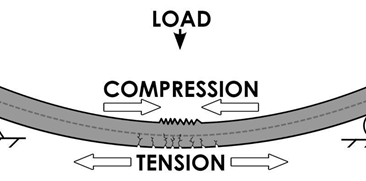
Regardless of the length, or height, all structures are subject to the forces of compression tension, bending and shear.
Compression and Tension
Both compression and tension are forces that are capable of damaging bridges in addition to other factors such as traffic and weather (e.g., rain and snow). Tension is the force that pulls materials apart while compression squeezes the material together. Dissipation enables the force to "spread evenly" across the entire bridge, while transference requires moving the stress "from an area of weakness to an area of strength." Bridge designers must consider these and other forces to ensure the structure counteracts the stresses and loads it is designed for.
Planning Considerations
Before beginning construction, engineers need to understand the problem at hand. Why is the bridge needed? How strong does it need to be for its intended use? Once forces and loads have been established, it is essential to determine the highest possible stress on the bridge. For example, a heavily-used bridge may be under significantly more stress (or force) in Florida during a hurricane evacuation. With all potential factors in mind, it is then that the engineering team can move onto calculating the types and amounts of material needed to resist the loads, and thus begin to design the bridge.
Components of a Bridge
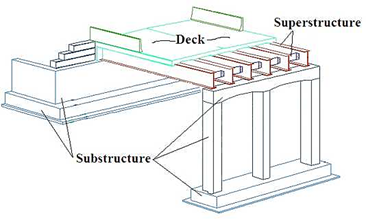
Photo Credit: Michigan Department of Transportation
SUBSTRUCTURE
The substructure of a bridge is the supporting structure below the deck, or upper construction. It includes piers, abutments, foundations, bearings, and other components. Hard requirements to consider during the design of the substructure include:
- Navigation Clearance Requirements – Involves minimum horizontal and vertical clearance requirements for navigation. These requirements will affect span lengths and heights, therefore the choice of the substructure type is impacted as well.
- Environmental Commitments – Includes the environmental permitting process. Location of the bridge and construction activities must be approved by the appropriate environmental agencies before the project begins.
- Surface Terrain – The terrain on which the bridge will be constructed influences the type of substructure needed in regards to, “geology, geometry, and constructability.”
Once the team has taken into consideration all outside factors that affect the project, engineers need to decide what type of foundation and overall substructure is best suited for structural capacity.
SUPERSTRUCTURE
The superstructure consists of the deck structure itself, which supports direct loads of traffic and, “all other permanent and variable loads to which structure is subjected.” It also includes girders, slabs, posts, cable-suspended systems, and additional elements above the main deck.
Superstructures need to be designed to uphold applied design loads (permanent and transient) as well as live and dead loads. There are many types of superstructures, though some that mainly use concrete are:
- Concrete Slab – Functional for short to medium span lengths, though the range of span lengths can be increased with the addition of slab structures.
- Prestressed Concrete Girder – Typically require little maintenance and are economical for projects but are limited in spans.
- Prestressed Box Girder – Usually more expensive than concrete slab structures but have the advantage of rapid construction and enable larger spans.
- Concrete Box Girder – These superstructures are mainly adaptable for urban sites.
- Concrete Rigid Frame –They are known for having significant aesthetic value.
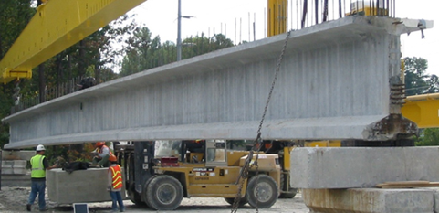
Concrete Girder. Photo Credit: Concrete Bridge Views
An important factor to consider is the aging of bridges, which primarily affects the deck due to normal wear and tear. In order to attain longevity in the bridge's lifespan, the deck needs to be maintained and preserved. This can be achieved through various kinds of deck overlays, such as UHPC.
Achieving Longevity with UHPC
Due to the high need for bridge repair and reconstruction and the limited funds available to do this work, there is a need for innovative concrete solutions. The vast majority of bridge decks in the USA consist of concrete and rebar. Engineering research universities have been studying alternate materials for bridge decks, such as fiber-reinforced concrete. In new construction, UHPC can be used as a deck riding surface for precast and cast-in-place concrete decks. In rehabilitation projects, UHPC makes an excellent, long lasting material when used as a deck overlay. In both cases, the long life span of UHPC deck surface can add decades to the lifespan of a bridge.
At UHPC Solutions, we understand that budgets and time constraints are potential obstacles when making decisions on bridge construction projects. Contact us today to learn more about why UHPC is an effective solution that provides reliable and durable results.